This is a quick tutorial how to enable external debug on PINE64's recent RK3566 single board computers named Quartz64. I've tested this on SOQuartz and Quartz64-A, but I reasonably expect this procedure to also work on Quartz64-B hardware as well as all other RK3566 products such as for example PineNote.
First let me say thanks to [1] for writing his blog article about external debugging on RK3328 (ROCK64). It was very helpful.
At the time of me writing this ( August of 2022 ) available Quartz64 boards have very limited software support available meaning they are currently targeted at developers.
This debugging method is particularly useful for kernel debugging. If you're looking to debug an userland application I suggest to use gdbserver over the network.
To the point.
What do you need?
Hardware
- A RK3566 Single Board Computer to debug. For example a SOQuartz with a suitable carrier board, or a Quartz64-A
- A fan and a radiator. The CPU idle states will be disabled during debugging which causes a lot more heating of the cores. A radiator and a fan are absolutely necessary.
- An eMMC module with an OS image. We will be disabling the sd0 interface to enable SWD functionality.
- A SWD hardware debug probe supported by OpenOCD. I'm using Jlink.
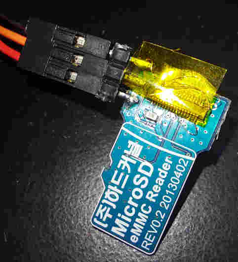
- Some way to connect to the SD card interface. I'm using a modified micro SD to eMMC adapter card.
Software
- GDB debugger compiled with arm 64 support.
- OpenOCD latest version
- Linux Kernel source tree for the board and the kernel compiled with CONFIG_DEBUG_INFO=y option. This is not strictly necessary, but makes your debugging experience a lot easier.
- devmem tool or any other way to write to arbitrary memory locations on Linux.
Physical connection
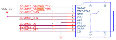
There are 2 debug interfaces on Quartz64 boards. There is the MCU JTAG and an ARM JTAG. This article focuses on debugging the Cortex-a55 ARM cores so we will be using the ARM JTAG pins. There are two JTAG pins exposed TCK and TMS. They share their functionality with sdmmc0 and uart5 interfaces as shown below.
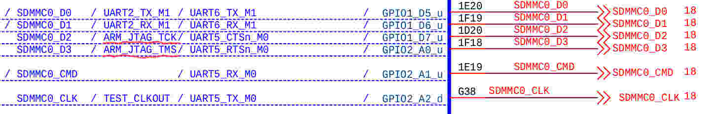
The exact function of the pins can be switched by using the chip's general registers. Those are the pins we need to connect to.
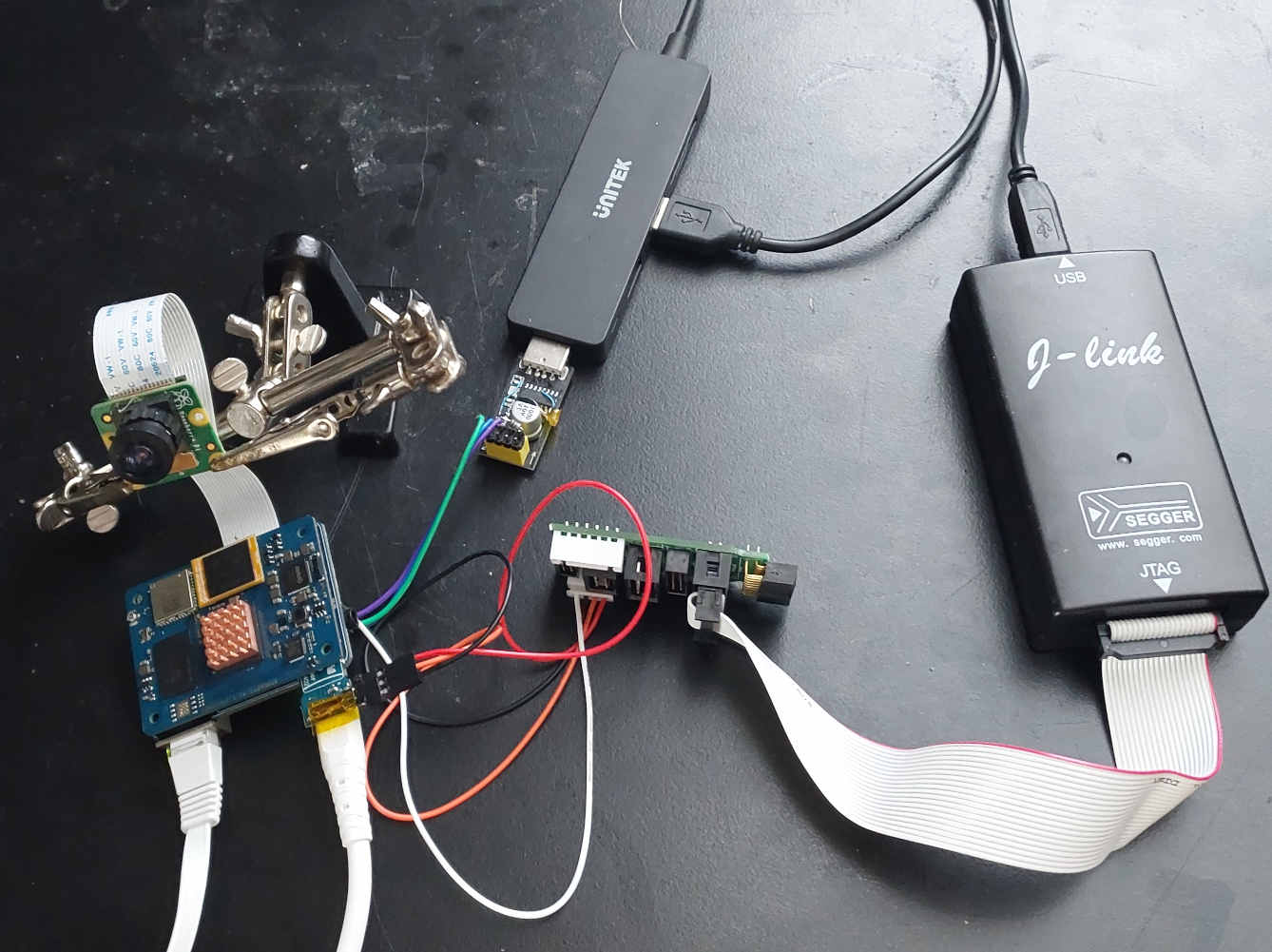
Here is an example how I connected to them using a cheap $1 micro sd to eMMC converter.
 You need to connect at least 3 pins. TCK to SCK, TMS to SDIO and GND. My Jlink debug probe also requires a voltage reference (Vref) to be connected to the IO voltage supply which in case of SD interface is 3.3V
It is important for the connection to be made with both the probe and the debugged device off.
Software and Configuration
I'll not be describing how to build latest gdb and openocd from source as it is well described in their respective documentation. From here I assume you have both.
First you need openocd config file for the target device. There is none for RK3566 at the moment so I've written the below as a start. Save the below as rk3566.cfg in the folder of your choice. If you use a different debug interface make sure to adjust first lines of the file to reflect that.
adapter driver jlink
adapter speed 1000
transport select swd

source [find target/swj-dp.tcl]
set _CHIPNAME rk3566

set _TARGETNAME $_CHIPNAME.cpu
set _ENDIAN little

swd newdap $_CHIPNAME cpu -ignore-version
dap create $_CHIPNAME.dap -chain-position $_CHIPNAME.cpu

cti create cti0 -dap $_CHIPNAME.dap -baseaddr 0x81014000 -ap-num 0
target create ${_TARGETNAME}0 aarch64 -dap $_CHIPNAME.dap -coreid 0 -cti cti0 -dbgbase 0x81004000
${_TARGETNAME}0 configure -work-area-size 0xffff -work-area-phys 0xFDCC0000 -work-area-backup 0

cti create cti1 -dap $_CHIPNAME.dap -baseaddr 0x81015000 -ap-num 0
target create ${_TARGETNAME}1 aarch64 -dap $_CHIPNAME.dap -coreid 1 -cti cti1 -dbgbase 0x81005000
#${_TARGETNAME}1 configure -defer-examine
${_TARGETNAME}1 configure -work-area-size 0xffff -work-area-phys 0xFDCC0000 -work-area-backup 0

cti create cti2 -dap $_CHIPNAME.dap -baseaddr 0x81016000 -ap-num 0
target create ${_TARGETNAME}2 aarch64 -dap $_CHIPNAME.dap -coreid 2 -cti cti2 -dbgbase 0x81006000
#${_TARGETNAME}2 configure -defer-examine
${_TARGETNAME}2 configure -work-area-size 0xffff -work-area-phys 0xFDCC0000 -work-area-backup 0

cti create cti3 -dap $_CHIPNAME.dap -baseaddr 0x81017000 -ap-num 0
target create ${_TARGETNAME}3 aarch64 -dap $_CHIPNAME.dap -coreid 3 -cti cti3 -dbgbase 0x81007000
#${_TARGETNAME}3 configure -defer-examine
${_TARGETNAME}3 configure -work-area-size 0xffff -work-area-phys 0xFDCC0000 -work-area-backup 0

target smp ${_TARGETNAME}0 ${_TARGETNAME}1 ${_TARGETNAME}2 ${_TARGETNAME}3

${_TARGETNAME}0 configure -event reset-assert-post "aarch64 dbginit"
${_TARGETNAME}1 configure -event reset-assert-post "aarch64 dbginit"
${_TARGETNAME}2 configure -event reset-assert-post "aarch64 dbginit"
${_TARGETNAME}3 configure -event reset-assert-post "aarch64 dbginit"

targets rk3566.cpu0
Then connect all the hardware and boot the board. Currently this article describes two ways to debug the system. Starting from u-boot, or starting from once the kernel has already booted. I much prefer the latter so I'll start with it first.
Once your target has booted connect to it and run the below in the root session.
echo "1" > /sys/devices/system/cpu/cpu0/cpuidle/state1/disable
echo "1" > /sys/devices/system/cpu/cpu1/cpuidle/state1/disable
echo "1" > /sys/devices/system/cpu/cpu2/cpuidle/state1/disable
echo "1" > /sys/devices/system/cpu/cpu3/cpuidle/state1/disable
devmem 0xFDC6001c w 0x70002110
devmem 0xFDC60020 w 0x00070112
Those commands disable cpuidle sleep states (that's why we need a radiator and a fan). Then they switch on the JTAG interface pins. Once you've run this you can start openocd on your development PC.
openocd -f rk3566.cfg
This is what is says on my system.
Open On-Chip Debugger 0.11.0+dev-00787-gb76a7a82b (2022-08-10-10:37)
Licensed under GNU GPL v2
For bug reports, read
http://openocd.org/doc/doxygen/bugs.html
Info : Listening on port 6666 for tcl connections
Info : Listening on port 4444 for telnet connections
Info : J-Link V9 compiled May 7 2021 16:26:12
Info : Hardware version: 9.60
Info : VTarget = 3.304 V
Info : clock speed 1000 kHz
Info : SWD DPIDR 0x2ba01477
Info : rk3566.cpu0: hardware has 6 breakpoints, 4 watchpoints
Info : rk3566.cpu1: hardware has 6 breakpoints, 4 watchpoints
Info : rk3566.cpu2: hardware has 6 breakpoints, 4 watchpoints
Info : rk3566.cpu3: hardware has 6 breakpoints, 4 watchpoints
Info : starting gdb server for rk3566.cpu0 on 3333
Info : Listening on port 3333 for gdb connections
Info : accepting 'gdb' connection on tcp 3333
Info : rk3566.cpu0 cluster 0 core 0 multi core
Info : rk3566.cpu1 cluster 1 core 0 multi core
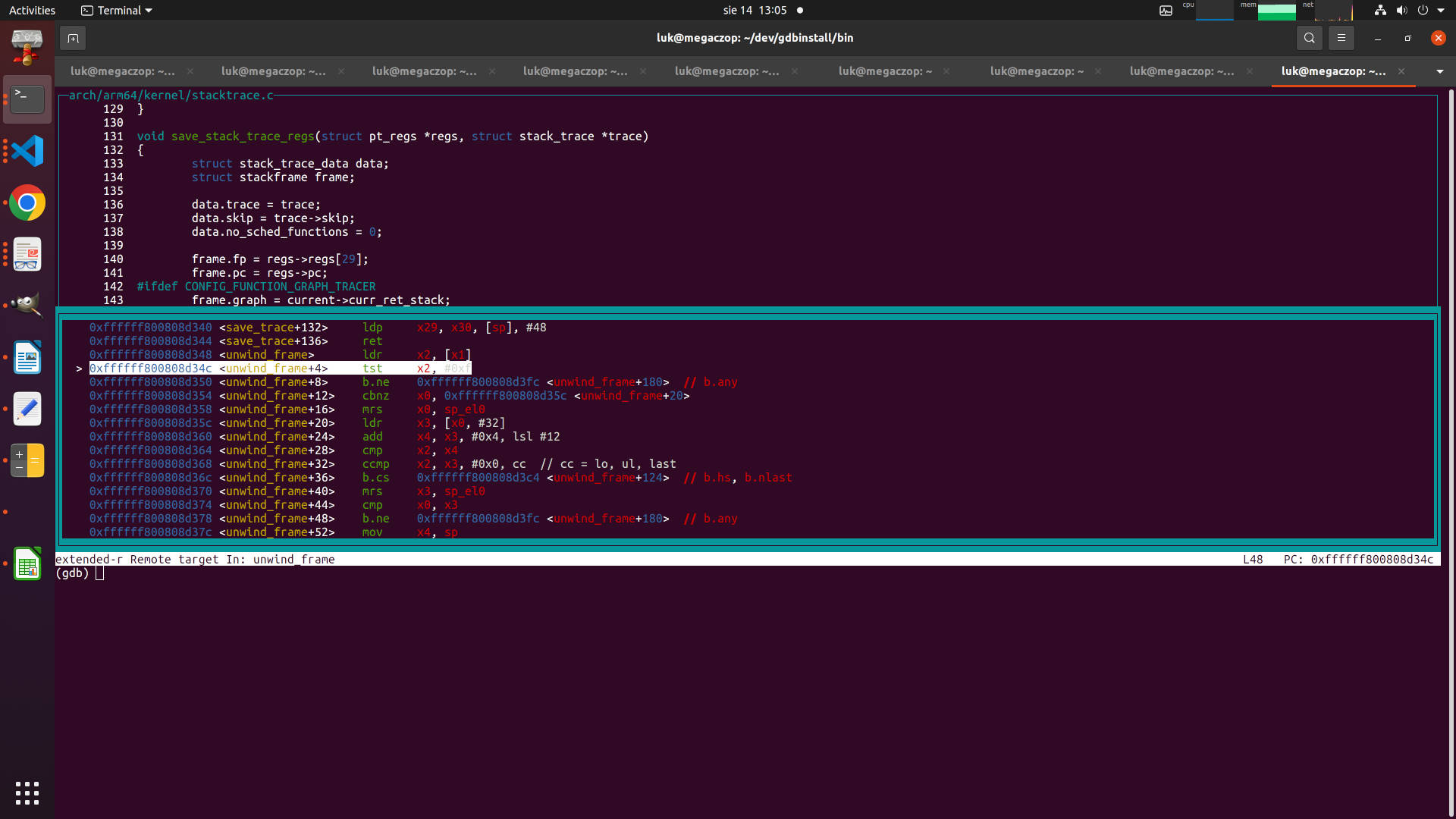
Then you can go to another terminal. Launch gdb specifying the path to the vmlinux file with the Linux kernel running on the device. Then issue the command.
target extended-remote :3333
Remote debugging using :3333
unwind_frame (tsk=0xffffffc0789e1d00, frame=0xffffff800fa63cf0) at arch/arm64/kernel/stacktrace.c:48
48if (fp & 0xf)
(gdb)
Now you can do your debugging. Note to use hbreak instead of break to use hardware breakpoints.
What if you need to debug initialization of a driver during boot? My recommendation is to compile the driver a a loadable module and load it once you have your debug session connected.
However for completeness sake I include another method to connect before Linux kernel boots using u-boot. If you choose this method you need to modify the rk3566.cfg config file by shifting comment mark to defer examine all cores other than the first as u-boot uses only core 0. To enable the debug interface from the u-boot command prompt run the following:
mw.l 0xFDC6001c 0x70002110
mw.l 0xFDC60020 0x70112
Then you can start the debug session by running openocd as described previously. Please note that when Linux boots it will bring up additional cores you will not see if you do just this. Also unless disabled the moment core0 enters one of the idle states your debug session will drop. So bear this in mind if you're planning to use this to debug the boot process.
That's all for now.
References:
[1] - https://crwulff.blogspot.com/p/rock64.html
[2] -- SOQuartz and Quartz64-A schematics downloaded from the PINE64Wiki
[3] -- RK3568 TRM Document part 1.